Recently, the research result of Prof. Gang Cheng's group " A universal and passive power management circuit with high efficiency for pulsed triboelectric nanogenerator" was published in the famous international journal Nano Energy (IF=15.548, JCR District 1).
Article link: https://doi.org/10.1016/j.nanoen.2019.104372
As an energy harvesting technology, TENG based on triboelectrification and electrostatic induction effect can directly convert various mechanical energy in the environment, such as wind, raindrops, water waves, human motion, etc., into electricity. Compared with the electromagnetic generator, it has higher energy conversion efficiency at low operating frequency. Compared with PENG, its output voltage and energy have increased 3–4 orders of magnitude, and its materials and energy sources are more extensive. Effectively combining TENG with electronic devices in specific working environments and developing self-powered electronic devices or systems will be the development direction of wearable electronic devices and sensors in the Internet of Things. However, due to the high voltage, low current, and alternating-current (AC) pulsed output characteristics, TENGs cannot supply power to electronic devices independently, continuously, and steadily. Power management circuits, and energy storage devices are needed for TENGs to achieve stable output.
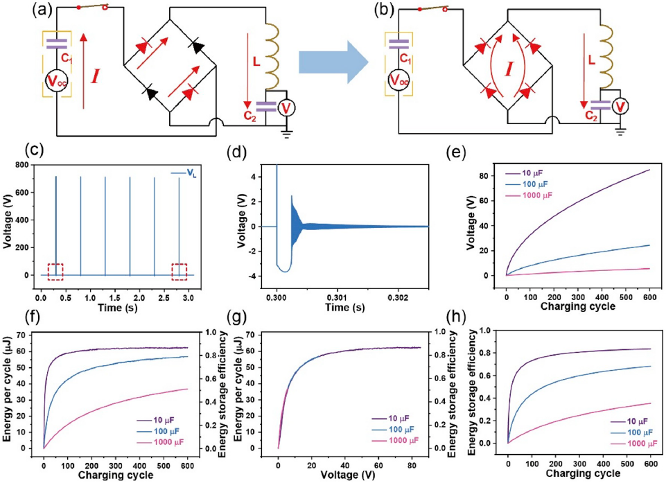
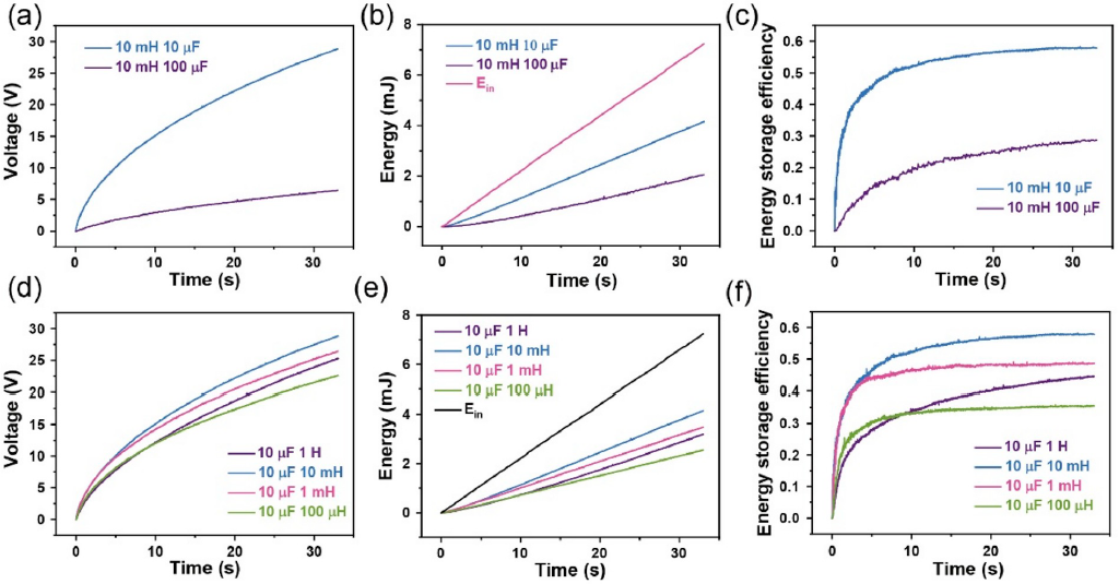
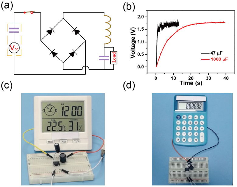
In this work, the output impedance characteristics of the Pulsed-TENG is firstly studied. The theoretical calculations show that the equivalent impedance of the Pulsed-TENG is zero. In the simulation, it is found that the output voltage and energy can still reach maximum when the matching impedance is 0.001 Ω. These prove that the equivalent impedance of the Pulsed-TENG is lower than 0.001 Ω and the output energy of the Pulsed- TENG can be kept maximally independent of the load resistance. Then, the energy storage efficiency of the passive power management circuit is studied through simulation and actual test. The simulation results show that the total energy storage efficiency can reach 83.6%. In the actual charging test, the energy storage efficiency is 57.8%. And the energy stored in this power management circuit can drive commercial calculator and temperature hygrometer. Based on the excellent impedance matching and high-frequency output characteristics of the Pulsed-TENG, the energy storage efficiency and speed can be greatly improved and the size of each component in the circuit can be reduced. Therefore, the system consisting of Pulsed-TENG and passive power management circuit will have broad application prospects in self-powered electronic devices and sensors of the Internet of Things.

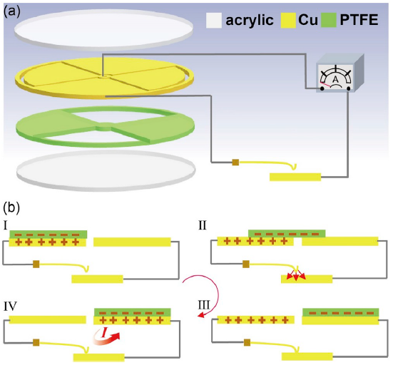
Fig. 1. (a) The structure diagram of Pulsed-TENG with an electrostatic vibration switch. (b) The working principle of Pulsed-TENG with an electrostatic vibration switch. (I) Initial state, (II) The electrostatic attraction force is smaller than the restoring force, (III) The electrostatic attraction force is greater than the restoring force, (Ⅳ) The charge transfer occurs.

Fig. 2. The energy transfer process of the passive power management circuit. Schematic diagram of the passive power management circuit in (a) first energy transfer stage and (b) second stage. The simulated (c) voltage of the inductor in the passive power management circuit and its magnification in (d) first charging cycles. Dependence of (e) the voltage of C2 and (f) the stored energy and energy storage efficiency per charging cycle on charging cycles. (g) Dependence of the energy and energy storage efficiency per charging cycle on the voltage of C2. (h) Dependence of the total energy storage efficiency on charging cycles.

Fig. 3. Actual test results of the voltage of C2, the stored energy, and the energy storage efficiency of the passive power management circuit. Dependence of (a) the voltage of C2, (b) the total stored energy, and (c) the energy storage efficiency of the passive power management circuit under different capacitors on time. Dependence of (d) the voltage of C2, (e) the total stored energy, and (f) the energy storage efficiency of the passive power management circuit under different inductors on time.

Fig. 4. Demonstration of the passive power management circuit for driving electronics. (a) Circuit diagram of the passive power management circuit for driving electronics. (b) Voltage curve when using the passive power management circuit with different capacitors to drive the temperature hygrometer. (c) Photograph of the normal work of the temperature hygrometer driven by the passive power management circuit. (d) Photograph of the normal work of the calculator driven by the passive power management circuit.
Master student Huaifang Qin and Dr. Guangqin Gu are the co-first authors of the paper, and Prof. Gang Cheng and Prof. Zuliang Du are the co-corresponding authors of this paper. This work was supported by funding from the National Natural Science Foundation of China, the Science and Technology Department of Henan Province and Henan University.